Lab 1: Dueling LEDs
Starts: Week 4 (Sep 13 - Sep 17)
Demo Due: Week 5 (Sep 20 - Sep 24)
Points: 50
Updates and Clarifications:
(if needed)
Datasheets and Manuals
Parts Needed for Lab (all parts are provided in your team's Parts Kit)
Lab Overview:
In this lab, you will learn the basics of the interfacing with external hardware with the PIC microcontroller, utilizing your soldering and wire wrap skills to integrate additional components with you PIC microcontroller, and using timers to make precise timing measurements.
NOTE: As you will be incorporating additional components with your PIC microcontroller, those components can either be directly integrated in the prototyping area of the 16-bit 28-pin Starter Board or using a separate prototype board. Each team is provided with a prototype board within their Parts Kits. If your team decides to integrate the components in the prototype area of the Starter Board, of the team member must be willing to use his/her board for this purpose.
Provided Software Code:
Lab 1 Procedure:
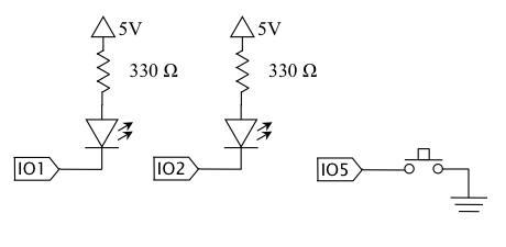
- Connect the 2 LEDs to IO1 and IO2 of the 16-bit 28-pin Starter Board. The anodes (long wire) of the LEDs should be connected to 5V through a 330 Ohm resistor. The cathodes (short wire) should be connected to the IO1 and IO2 inputs.
- Connect the momentary tactile switch to IO5 of the 16-bit 28-pin Starter Board. The momentary switch has two poles but four pins. Two the pins on each side of the switch are connected together. Using the continuity measurement of your multimeter, determine which pins correspond to the two poles of the switch. Connect one side of the switch to ground and the other (non connected) side to IO5.
- A schematic for the required circuit is provided:
- Using the provided C code template (lab1p1.c) for Part 1 of this lab, write a software program with the following requirements:
- The LEDs should be organized in such a way that they can be differentiated as a Right LED and Left LED.
- Initially, the Right LED should be illuminated.
- For every distinct press of the switch, the LED being illuminated should be alternated. For example, if the Right LED is currently on, the Right LED will be turned off and the Left LED will be turned on.
- Both the button press and button release should be debounced in software using precise 5 ms delay. This delay should be controlled using Timer1 of the PIC microcontroller.