Lab 2: Stopwatch
Starts: Week 6 (Sep 27 - Oct 01)
Demo Due: Week 5 (Oct 4 - Oct 08)
Points: 50
Updates and Clarifications:
(if needed)
Datasheets and Manuals
Parts Needed for Lab (all parts are provided in your team's Parts Kit)
Lab Overview:
In this lab, you will build a stopwatch capable of timing minutes, seconds, and 1/100th of seconds with basic start, stop, and reset controls. This lab assignment will interface with a 8x2 character LCD display and require the use of interrupts for precise timing, and bit masking operations to access 4-bit simultaneously from a single port (PORT B).
NOTE: As you will be incorporating additional components with your PIC microcontroller, those components can either be directly integrated in the prototyping area of the 16-bit 28-pin Starter Board or using a separate prototype board. Each team is provided with a prototype board within their Parts Kits. If your team decides to integrate the components in the prototype area of the Starter Board, of the team member must be willing to use his/her board for this purpose.
Provided Software Code:
Lab 2 Procedure:
- Part 1: LCD Interface and Software Driver
- Connect the 8x2 LCD Display to the PIC24F using the provided schematic:
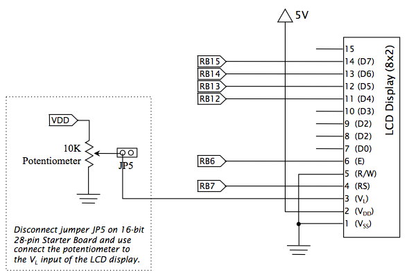
Note: The VL input of the LCD Display is used to control the contrast of the display. The 16-bit 28-pin Starter Board has a 10K potentiometer that can be used to adjust this contrast. To connect the potentiometer, you can connect to jumper JP5. - Using the provided C code (lab2.c, lcd.h, lcd.c) complete the software driver code required to interface with the LCD. This C code includes a simple demonstration program that will utilize the LCD software driver to print sample messages on the LCD. The provided C code for the LCD software driver (lcd.c) provides specific instruction within the comments on what additional functionality must be incorporated. These required modification are marked with TODO. To complete the software driver, you will need to complete the following:
- Develop a DelayUs() function that will utilize Timer 2 to create a user specified delay in microseconds provided as function parameter.
- The LCD software driver utilizes a 4-bit interface to write 8-bit values as two consecutive 4-bit write operations. Complete the WriteLCD() function to write the most significant 4-bits followed by the least significant 4-bits to the LCD_D output. Your code should utilized the LCD_D #define defined within the provided code to write data to the LCD. You will need to utilize bit masking and shifting operations to perform these writes.
Hint: An example of how to utilize bit masking and shift operations can be found within the LCDInitialize() function. - The initial steps needed to configure the LCD Display to utilize a 4-bit interface have been provided. Complete the LCDInitialize() function to configure the operational mode of the LCD. Details of the initialization process and control instruction needed to configure the display are explained within the LCD Display Datasheet.
Note: Pay close attention to the requires delays needed for various control operations.
- Complete the LCDClear() function to clear the LCD display using the appropriate control instruction.
Hint: This functionality should the same as the clear display operation you are required to add the LCDInitialize() function.- Complete the LCDMoveCursor() function that will move the cursor to the user specified (x,y) coordinate. This operation must be performed using a single control instructions. As the move cursor control instruction depends on the format of the display, careful attention must be paid to utilize the correct control instruction for the 8x2 display format. This information can be found within the LCD Display Datasheet.
- Complete the LCDPrintChar() function for displaying a single ASCII character on the LCD Display.
Hint: This functionality can be easily achieved using the various functions already implemented.
- Connect the 8x2 LCD Display to the PIC24F using the provided schematic:
- Part 2: Implement Stopwatch Functionality
- Connect two momentary tactile switches to any two available inputs of the PIC24F that support change notifications. Ports supporting change notification are labeled on the PIC24F pin diagrams with CN.
Hint 1: You can utilize SW1 of the 16-bit 28-pin Starter Board as one of the required switches.
Hint 2: To avoid requiring software methods to debounce your button inputs, consider using hardware circuitry to debounce your buttons inputs. Refer to the circuit used for the connecting SW1 of the 16-bit 28-pin Starter Board.
- Using the software driver you created to interface with the LCD Display, develop a program to implement a basic Stopwatch, with the following requirements:
- The Stopwatch wil have to user inputs from the momentary tactile switches for Start/Stop and Reset.
- The Start/Stop input will be utilized to start and stop the execution of the Stopwatch. When stopped, the current time will be maintained, such that when the Stopwatch is started again, the timing will continue from the current time.
- When the Stopwatch is started, the top line of the LCD Display should display "Running:". When the Stopwatch is stopped, the top line of the LCD Display should display "Stopped:".
- The Reset input will be utilized to reset the current time back to 0 when the stopwatch is stopped. If the stopwatch is started (i.e. running), the Reset input should be ignored.
- A change notification interrupt must be utilized to detect user inputs for the Start/Stop and Reset inputs.
- The Stopwatch must have an accuracy of 1/100th of a seconds (i.e. 10 milliseconds). The bottom line of the LCD Display will be utilized to display the current time using the format MM:SS:FF, where MM is the current minute, SS is the current seconds, and FF is the current 1/10th ad 1/100th of a second.
- A interrupt using Timer 1 must be utilized to control the timing of the Stopwatch.
- Connect two momentary tactile switches to any two available inputs of the PIC24F that support change notifications. Ports supporting change notification are labeled on the PIC24F pin diagrams with CN.