Main
Lab 4: DC Motor Controller
UNDER DEVELOPMENT, PLEASE CHECK BACK LATER FOR UP-TO-DATE DESCRIPTION
Starts: Week 10 (Oct 25 - Oct 29)
Demo Due: Week 11 (Nov 01 - Nov 05)
Points: 50
Updates and Clarifications:
(if needed)
Datasheets and Manuals
Parts Needed for Lab (all parts are provided in your team's Parts Kit)
1 - H-Bridge L293B
2 - Motor Kits
Male Headers
4x4 Vector Prototype Board
Lab Overview:
In this lab, you will build a DC motor controller that utilizes a potentiometer and momentary switch to control the direction and speed of two DC motors.
Provided Software Code:
No Source Code (you're on your own this time)
Lab 4 Requirements:
The following provides a list of requirements for this lab assignments. No required procedure is defined for this lab. Groups will receive credit for implementing each of the following requirements.
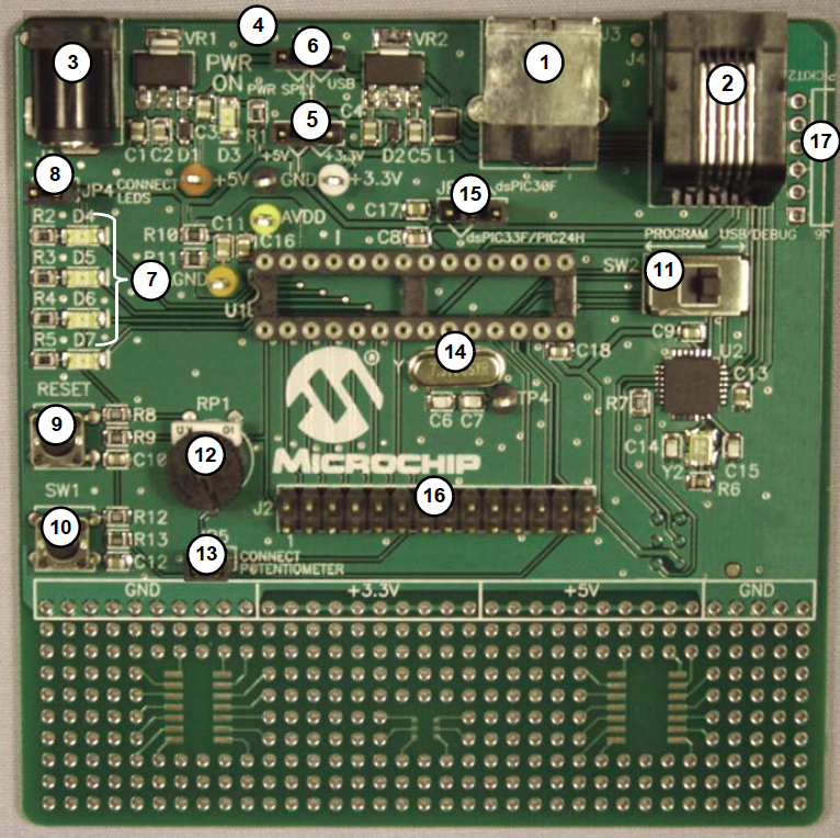
- The potentiometer (labeled 12 in the following picture) on the 16-bit 28-pin Starter Board should be utilized to control the speed of the DC motors. Analog to digital conversion must be utilized to determine the potentiometer position. \\
- If the potentiometer is the middle, both motors should operate at maximum speed in the current direction.
- If the potentiometer is turned fully to the right, the left motor should operate at full speed, and the right motor should be stopped (this will achieve maximum turning in the right direction).
- If the potentiometer is turned fully to the left, the right motor should operate at full speed, and the left motor should be stopped (this will achieve maximum turning in the left direction).
- All potentiometer positions between these settings should correspond to fractional values for the direction and control of the motors. In other words, your software should provide a smooth, continuous transition between all operating directions.
- A momentary switch should be utilized to switch between three operating states, Idle, Forward, Backwards.
- For every distinct button press, the operating states should cycle through the sequence, Idle, Forward, Idle, Backwards (repeat).
- In Idle mode, both motors should be stopped.
- In Forward mode, the motors should move in a forward direction subject to the direction control defined above.
- In Backward mode, the motors should move in a backward direction (i.e. opposite direction of Forward mode) subject to the direction control defined above.
- Pulse width modulation (i.e. output compare module) must be utilized to control the speed of the motors. No credit will be awarded if loops and delays are utilized for controlling the motor speed.
- The H-Bridge must be utilized to interface with the DC motors. The DC motors should be mounted (using double sided tape provided in lab) to the 4x4 Vector Prototype Board. Male headers should be utilized for connecting the circuit on the 4x4 header board to the 16-bit 28-pin Starter Board.
- The DC motors operate using a 9V power supply. An external 9V power source should be connected to the H-Bridge to provide the required voltage and current to drive the DC motors.
NOTE: Before applying power to your circuit, please check the TA to ensure you have properly connected the circuit.