Lab 3: FSM for 4-bit Up-then-Down Counter
Starts: Week 6 (Sep 28-Oct 02)
Demo Due: Week 7 (Oct 05-Oct 09)
Code Due: Friday, Oct 09, 11:59PM
Points: 85
Pre-Lab Assignment
Create and state diagram for the 4-bit Up-then-Down Counter design described below. (10 points)
Code-Check Requirement
An initial implementation for all Verilog modules and testbenches required for this lab assignment must be shown to your TA at the beginning of your scheduled lab section during Week 7 (Oct 05-Oct 09). (5 points)
Files
Lab Overview
In this lab, you will design a 4-bit Up-then-Down Counter and interface the up-then-down counter with your binary to 7-segment LED decoder designed in Lab 2. The 4-bit up-then-down counter design has four inputs, Clk, Rst, Enable, Short, and a 4-bit output Cnt, represented by the four outputs Cnt3, Cnt2, Cnt1, Cnt0. If Rst is 1, the counter should reset its count value to one (0001). Otherwise, if Enable is 1, on every clock cycle the counter should first count up from 1 to 10 and then back down to 1 repeatedly when Short is 0. If Short is 1, the counter should behavior in a similar manner, except that it should count up from 1 to 5 and then back down to 1 repeatedly. If Enable is 0, the counter should keep its present value.
UPDATE: If the count value is greater than 5 when Short is set to one, the short count will not take effect until the count drops below 5.
In order to download your 4-bit up-then-down counter implementation to the Spartan-3E FPGA board, you will need to interface your counter with the binary to 7-segment LED decoder designed in Lab 2. Furthermore, the 50MHz clock integrated within the Spartan-3E FPGA board operates too quickly to be able to view the counter output on the 7-segment LED display. As such, you must also interface with the clock divider component provided with this lab. The clock divider, ClkDiv, has two inputs, Clk and Rst, and one output, ClkOut. Given the 50 MHz clock provided by the Spartan-3E FPGA board, the ClkDiv component will generate a 1 Hz clock on its output, ClkOut. This 1 Hz clock can then be connected to the input of your 4-bit counter.
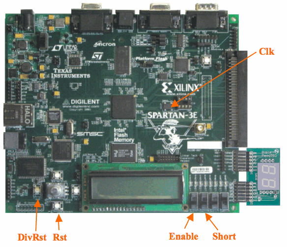
The figure to the above right provides an overview of the connections that will be used to implement your 4-bit Up-then-Down Counter on the Spartan-3E FPGA board. The overall counter implementation will have a single Clk input provided by the 50 MHz oscillator integrated on the Spartan-3E FPGA Board, two reset inputs – one for the clock divider (DivRst) and one for your 4-bit Up-then-Down Counter (Rst), and Enable and Short inputs connected to your 4-bit Up-then-Down Counter. The implementation will also interface with your binary to 7-segment LED display using the outputs to the individual segment of the 7-segment LED display. The following is a partial .ucf file providing the connection details for the new inputs and outputs needed for the 4-bit Up-then-Down Counter (you will need complete the .ucf file to properly connect to the 7-segment LED display):
NET "Rst" LOC = "K17" | PULLDOWN;
NET "DivRst" LOC = "D18" | PULLDOWN;
NET "Enable" LOC = "N17";
NET "Short" LOC = "H18";
# Enter additional connections below
Lab Procedure
- Behaviorally design the 4-bit Up-then-Down Counter as a Finite State Machine (FSM). You FSM design should consist of two always procedures. The first always procedure, should implement the state register. The second always procedure should implement the FSM control logic. In the design of the FSM control logic, you must use a case statement to describe the combinational behavior associated with each state. (25 points)
- Create a testbench to test your design for correct functionality. Your testbench should be self checking using if statements and the $display task to report any errors during simulation. At a minimum, the self checking testbench should test the following cases (20 points):
- Check that counter counts up then down correctly (4 points)
- Check for correct wraparound functionality for counting up and down (4 points)
- Check for correct reset behavior from non-one count value (4 points)
- Check for correct enable behavior (4 points)
- Check for correct short counting behavior (4 points)
- Create a new top-level component that structurally connects your 4-bit Up-then-Down Counter with the clock divider, ClkDiv, and your binary to 7-segment LED decoder. Complete the provided .ucf file and synthesize your 4-bit Up-then-Down Counter. Download and test your design on the Spartan-3E FPGA board for correct functionality. At a minimum, you should test the same cases as your self checking testbench. (25 points)
