Lab 2: Binary to 7-segment LED Decoder
Starts: Week 4 (Sep 15-Sep 19)
Demo Due: Week 5 (Sep 22-Sep 26)
Code Due: Friday, Sep 26, 11:59PM
Points: 75
Pre-Lab Assignment
Create a truth table and corresponding Boolean equations implementing the desired functionality of the binary to 7-segment LED decoder design. (10 points)
Files
Lab Overview

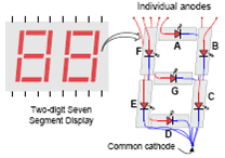
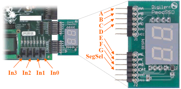
In this lab, you will build a decoder to display the hexadecimal digit of 4-bit binary number on a 7-segment LED display. The binary to 7-segment LED decoder has four 1-bit inputs In3, In2, In1, In0, and seven 1-bit outputs A, B, C, D, E, F, G, for controlling the seven segment of the LED display as shown in the figure to the right. Based on the input values the decoder will illuminate the correct segments of the LED display to output the single hexadecimal digit corresponding to the binary input value. For example, if our input is 0000, we should output ABCDEFG = 1111110 to illuminate all LED segment except the middle segment, thereby displaying the digit 0.
The binary to 7-segment LED decoder will have one additional output to control which of the two 7-segment LED displays will be illuminated. Only one 7-segment LED display can be illuminated at any given time. Your design should include a 1-bit SegSel output to control which display to use. You will also need to determine what value should be assigned to the SegSel signal to illuminate the right (or top depending on your orientation) 7-segment LED display. You can determine this setting by either reading the datasheet for the 7-segment display module or experimentally determining this value.
In order to download your decoder to the Spartan-3E FPGA board you must map the inputs and outputs of the binary to 7-segment decoder to specific components. For this project we will map the input signals to the slide switches and map the output signals to the 7-segment LED display, as shown above. The corresponding .ucf file is:
NET "In2" LOC = "H18";
NET "In1" LOC = "L14";
NET "In0" LOC = "L13";
NET "A" LOC = "B4";
NET "B" LOC = "A4";
NET "C" LOC = "D5";
NET "D" LOC = "C5";
NET "E" LOC = "A6";
NET "F" LOC = "B6";
NET "G" LOC = "E7";
NET "SegSel" LOC = "F7";
Lab Procedure
- Implement the binary to 7-segment LED decoder behaviorally expressing each output as a Boolean equation in Verilog. (15 points)
- Using a testbench, simulate your binary to 7-segment LED decoder to exhaustively test all possible input combinations. (15 points)
- Synthesize and download your binary to 7-segment LED decoder to the Spartan-3E Starter board and test your design exhaustively by trying all possible input combinations. (30 points)
- Determine which output setting of SegSel will illuminate the desired LED display. Re-synthesize and download your modified design if necessary. (5 points)
